Inventor fusion or AutoCAD revisit? follow-up
Does Autodesk really make the fusion between linear and non linear modeling? If so how did they do that?
So here my point of view that follow my first post on the topic.
The new Fusion preview 2 stuff is mainly about the Change manager, that seem to make the fusion, the link, the bridge or call it what ever you want….
Not having a direct access to inventor 2010, i rely on the review on the net, so here the typical workflow that seem to make the consensus for now.
1- You start your design in Inventor, save the IPT file.
2- File is open in fusion to receive some treatments, then save has a DWG file.
3- DWG file is open inside Inventor. Path to the original IPT file is recognize
4- Once the path is resolve, Change manager compare both files (original IPT and the new DWG)
5- User review the Change manager list and apply the treatments
6- File is then save ( i guess that old IPT is update or squash in the operation)
To have a more in depth coverage of the process read Deelip – Inventor Fusion Technology Preview 2 it is a series of 10 articles on the subject or Develop 3D also you can read Paul Hamilton blog .
Now how Change manager can fill the gap between linear and non linear modeling?
In Fusion when you create extrusion you can chose between, adding, removing, intersecting and….. add a new body
For peoples that did not notice, at the top of the feature tree, there is a section listing all the bodies present in the document.
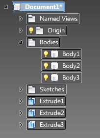
I do not have a copy of inventor 2010, but did get the opportunity to see this new version and there is some screen shoot all around, here one taking from Develop 3D
Do you notice something familiar….

The solid Bodies section.
This section, is the one that catch my attention has it seem to be the common point between the linear modeling of Inventor and the non linear modeling of Fusion and the link to make the transition between the IPT and the DWG.
What it is store in that section? My best bet, it is the raw information of the kernel.(shape manger that is a derivate of ACIS from spatial). From there it could be easy to track informations. Roughly said, I’m not an expert on kernel, all geometries has an entry to the kernel database, each edges, faces has a unique number that can help track who is associate to who. Not sure about this one, but it will be fair to think that Autodesk use Shape manager for it kernel inside AutoCAD.
From the kernel point of view, a face in inventor or in fusion or in Autocad is the same.
With this information Change manager can compare (step 4) face_001 in the DWG ( step 2), to the same face definition in the IPT ( step 1). From here it is possible to look at what feature use face_001, analyze the move direction ( compare face normal) and see if the feature allow that kind of move.
From Deelip review we see that if a simple block has one of it’s face tilt, Change manager do not recognize this has being a move you can do in the extrusion. Instead two sculpt features were add. May be in a later edition they will recognize this has a draft feature? This would then involve feature recognition.
I wonder if Deelip could do the same move, but with the bottom surface? would we have the same result?
What about rotating the whole body and see if the sketch plane would adapt? Start with a simple situation, make sure the rectangle is center and rotate around one of the axis. May be the blue one to start and see what will happen to the sketch.


So from here what can i say.
Do we have the fusion between both world? I would prefer to say that a bridge was create to allow information’s to go from one bucket to another one.
Because of the Fusion side we may call this non linear modeling but when it is back to Inventor, we rely on a plane/sketch combination to maintain part integrity, therefore what happen to the fusion?
If Autodesk keep the same logic of outputting the change to a DWG, what do we do with it? erase it?
Assuming Fusion is merging inside inventor, do we get a non-linear modeler or we simply get a superset of features to make a parametric history based edit? Some kind of SolidWorks’ Instant3D or what is call inside Solid Edge Dynamic edit/direct editing ( peer variables can be use for assembly). This may come with a litle extra has feature could eventually be recongnize or build (sculpt surface)
So at the end the main question from first article stand, does fusion stand for unite the linear and non linear world or what I suspect, is that internally Autodesk has start unite (fusion) their technologies to form a single platform for all their products?
I would be more incline to think the second one, with Fusion preview 2, they show they can make a bridge between Inventor (IPT) and Autocad (DWG). For those who follow Autodesk products, Autocad new features are geometric constraints and parametric dimensioning…………..
Update: after posting Isaw new entry from Paul hamilton,
No comments yet.
Solid DNA RSS

Solid Edge Virtual Training


Leave a comment